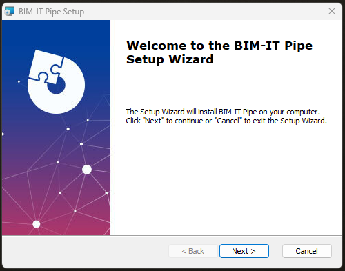
Run the installation file.
The installation wizard will appear. Follow the steps to complete the installation:
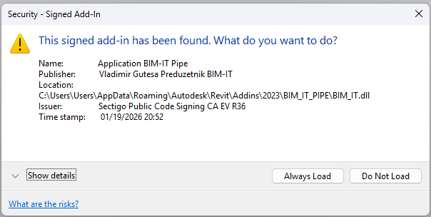
When you start Revit for the first time after installing BIM-IT Pipe, a security dialog will appear. Select Always Load:
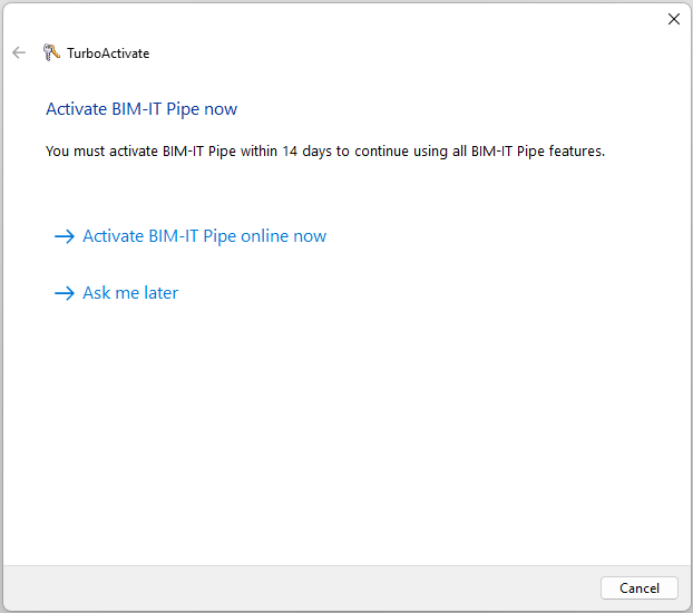
You can enter a serial number or continue in trial mode:
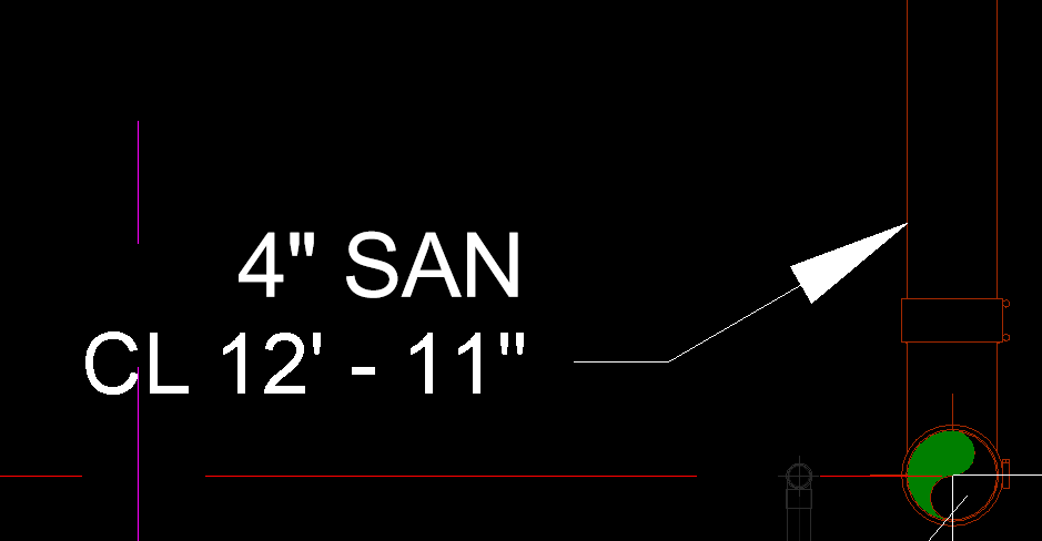
Sometimes there may be extra spacing between the elevation tag and the pipe size tag.
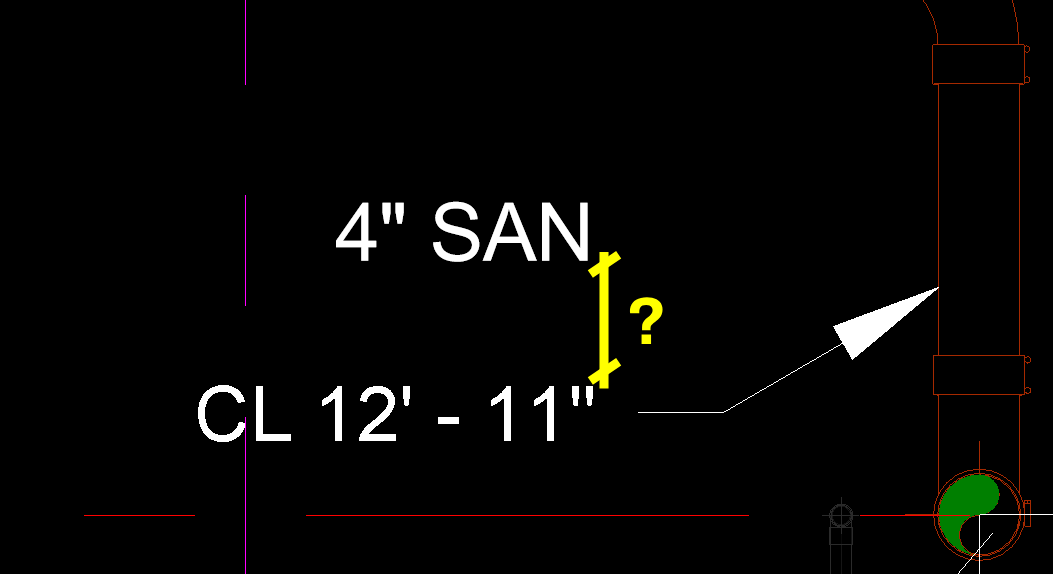
If the label wraps to two lines, the calculated height increases and spacing grows.
Stretch the label so text stays in one line.
Reload family and run tool again.
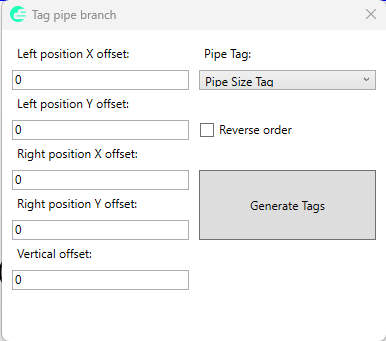
First select existing spot elevation and then branch of pipes you want to tag. Define offsets if needed and generate tags. The order of the tags will be defined based on the selected pipes order. Select Reverse order check box to reverse tags order.
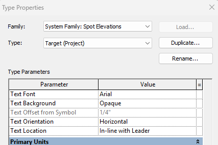
If there is an extra space between the elevation tag and the pipe size tag, you will need to edit tag family.
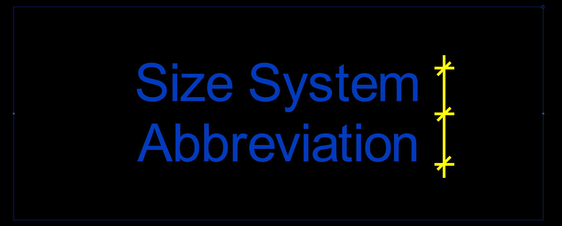
If the original tag family label is too small to fit the text on a single line, Revit wraps the text into two lines. In that case, the total label height is used for the position calculation, which results in increased spacing.
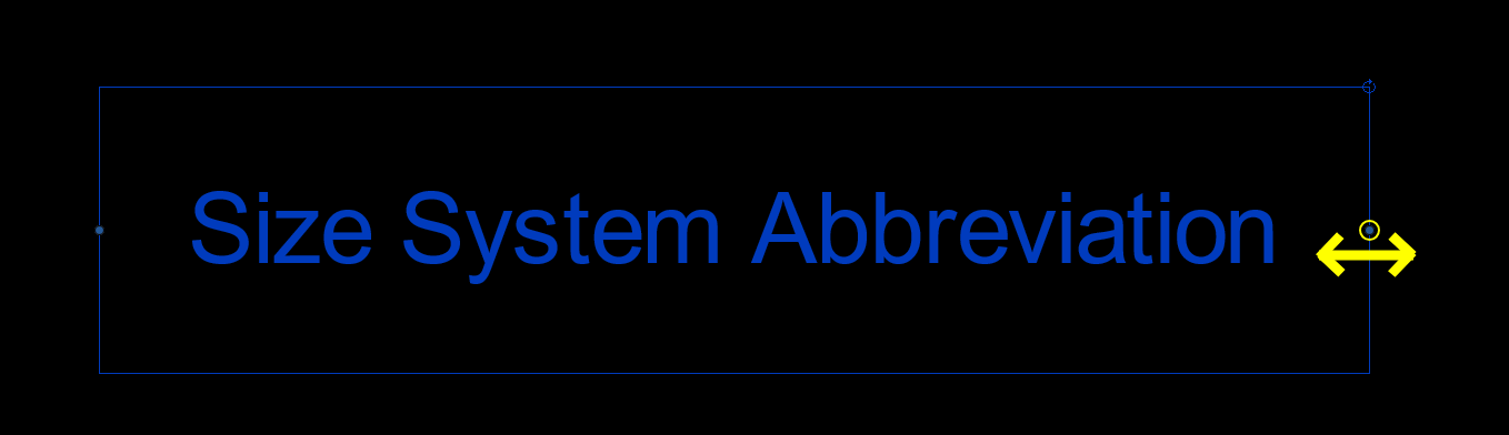
To avoid this behavior, edit the Pipe Size Tag family and stretch the tag label so that the text fits on a single line.
Reload the tag family into the project and run the Pipe Size Tag tool again.
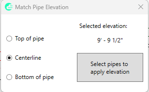
All pipes on which elevation was applied will inherit Reference Level from base pipe (first selected pipe). The tool is not working on pipes with a slope.
First select the reference pipe or line, and then the section view you want to align.
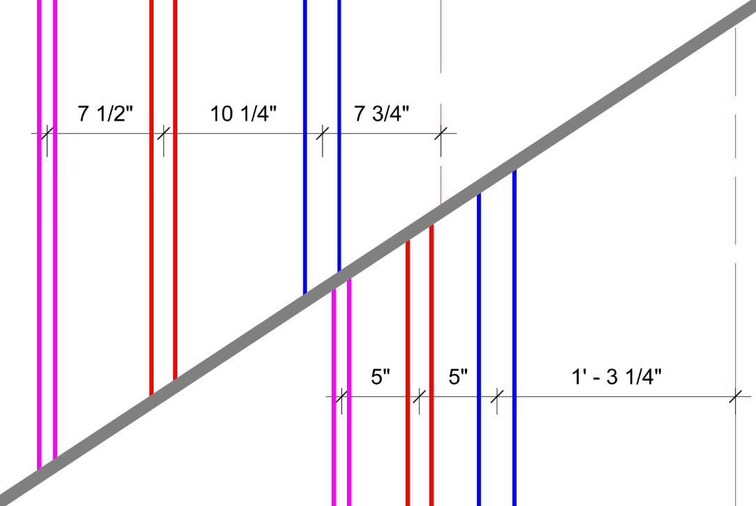
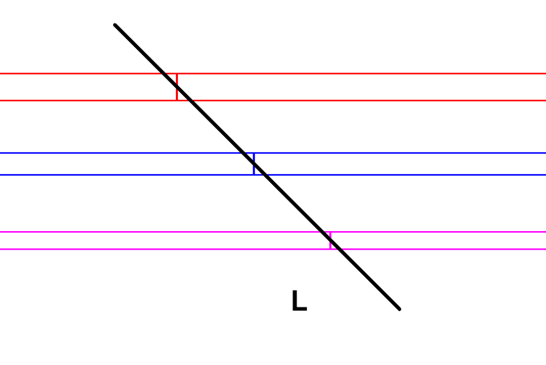
Run the tool, select the pipes, confirm the selection, and then pick a point. The tool will split all selected pipes at the intersection with an infinite line that passes through the selected point and is perpendicular to each pipe.
Run the tool, select the pipes, confirm the selection, and then pick a point. The tool will split all selected pipes at the intersection with a vertical infinite line passing through the selected point.
Run the tool, select the pipes, confirm the selection, and then pick a point. The tool will split all selected pipes at the intersection with a horizontal infinite line passing through the selected point.
Run the tool, select the pipes, confirm the selection, and then select the line. The tool will split all selected pipes at the intersection with the selected line.
First select reference pipes with the systems you want to isolate. Confirm selection to apply isolation.
Reverses the effect of the 'Isolate by System Type' tool.
The Insulation by Size and System Type tool allows you to define multiple rules and apply them automatically across the model - ensuring consistency and saving significant time.
Instead of manually selecting pipes and applying insulation one by one, you can define rules based on:
Once defined, the tool processes all matching elements and applies the correct insulation automatically.
Use the upper section of the dialog to define filtering criteria and insulation properties. After defining a rule, click Add to include it in the list.
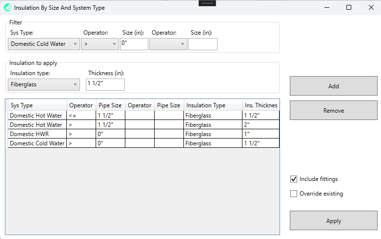
You can define multiple rules for different combinations of systems and pipe sizes. The rules will be applied sequentially.
The grid shows all defined rules, including system type, pipe size conditions, insulation type, and thickness.
Click Apply to execute all defined rules. The tool will process pipes (and optionally fittings) and apply insulation accordingly.
After execution, a report is displayed showing the results of each rule.
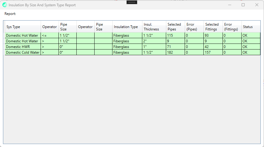
The report includes:
For example, you can define rules such as:
This allows you to standardize insulation across the entire model with a single click.
If insulation is hidden in the current view, the tool will make it visible and vice versa.